-
- Week11 Overview
- My Personal assignment
- Summarize the core knowledge points of Input Devices.
- Tools、Software & Machine Introduction
- Input conmponents:DHT11
- Programming Process
- Some Problems and Solutions
- Using the Oscilloscope to Measure waveforms
- The Hero Shots
- Team assignment
- Assignment files
week11-Input Devices
Week 11 - Overview
Learning Summary
1. Device Types
Introduction to various input devices such as sensors for temperature, light, motion, and distance, as well as switches and potentiometers.
2. Integration and Programming
Guidance on integrating these devices with microcontrollers and programming them for data capture and interaction.
3. Applications
Demonstrations of how these devices can be applied in real-world projects and systems.
Individual Assignment
- Add a sensor to a microcontroller board that you have designed.
- Read data from the sensor.
Group Assignment
- Probe an input device's analog levels and digital signals.
Reference Links
Week11 Input Devices Guide for my Fab Academy Journey.My personal assignment
1.Summarize the core knowledge points of Input Devices.
In this lesson, I learned about a variety of input sensors, including analog and digital signal inputs.
There are many types, involving the collection of various data, which is very interesting.
1. Temperature Sensors
- LM35: A precise analog temperature sensor.
- DS18B20: A digital temperature sensor with a 1-Wire interface.
2. Light Sensors
- LDR (Light Dependent Resistor): Simple and responsive to light changes.
- BH1750: A digital light sensor providing precise measurements.
3. Motion Sensors
- HC-SR501: A PIR motion sensor for detecting movement.
- MPU6050: An accelerometer and gyroscope module for motion tracking.
4. Distance Sensors
- HC-SR04: An ultrasonic sensor for measuring distances to objects.
- VL53L0X: A laser-ranging module for precise distance measurement.
5. Switches
- Tactile Switch: A basic push-to-make switch.
6. Potentiometers
- 10k Rotary Potentiometer: A variable resistor for adjusting levels in circuits.
2.Tools、Software & Machine Introduction
Software:Kicad
KiCad is a free and open-source electronics design automation (EDA) suite.
It features schematic capture, integrated circuit simulation, printed circuit board (PCB) layout, 3D rendering, and plotting/data export to numerous formats.
KiCad also includes a high-quality component library featuring thousands of symbols, footprints, and 3D models.
KiCad has minimal system requirements and runs on Linux, Windows, and macOS.
Learn the various functions of KiCad.


Arduino IDE:
Arduino IDE (Integrated Development Environment) is an open-source software used for writing and uploading code to Arduino-compatible boards.
It provides an easy-to-use environment for both beginners and professionals to develop various electronic and robotic projects.
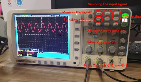
Tools:oscilloscope An oscilloscope is a crucial tool in electronics, enabling the visualization of electrical signal voltages as waveforms over time.
It offers various features:
• Display: Shows electrical signals as waveforms, with voltage on the vertical axis and time on the horizontal axis.
• Channels: Allows multiple signals to be viewed simultaneously.
• Bandwidth: Determines the frequency range the oscilloscope can measure accurately.
• Sampling Rate: The rate at which the oscilloscope samples the signal, crucial for capturing fast-changing signals.
• Triggering: Stabilizes repeating signals by starting data capture at a specific signal point.

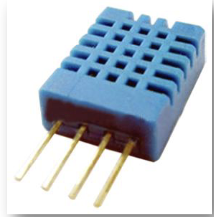
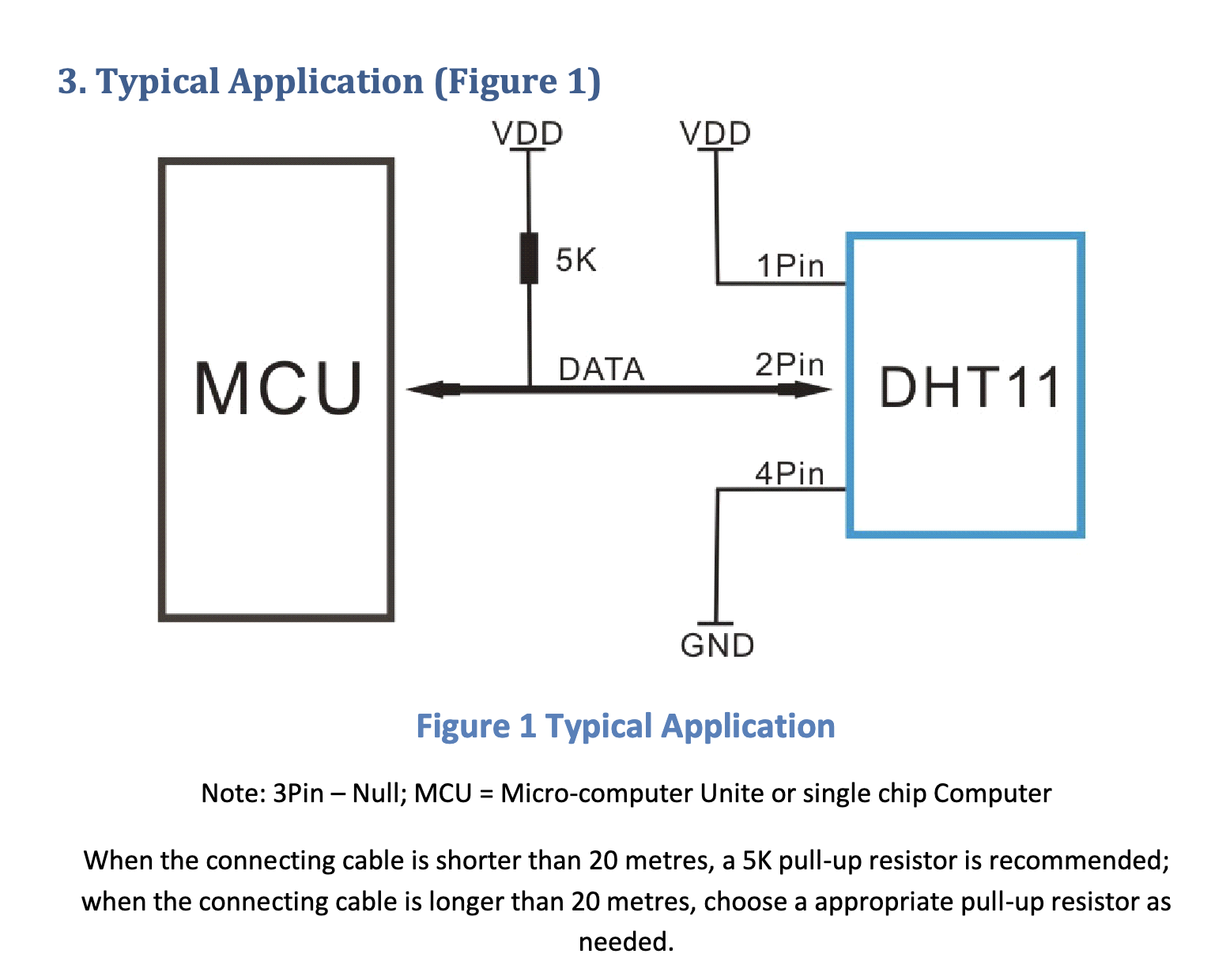
3.Input conmponents:DHT11
The DHT11 is a basic, ultra-low-cost digital temperature and humidity sensor.
It uses a capacitive humidity sensor and a thermistor to measure the surrounding air, and outputs a digital signal on the data pin (no analog input pins needed).
It’s simple to use, but requires careful timing to grab data.
Here are its key features:
- Temperature Range: 0-50°C with ±2°C accuracy
- Humidity Range: 20-80% with ±5% accuracy
- Operating Voltage: 3 to 5V
- Communication Protocol: Single-wire digital signal
From the component library, locate the schematic symbols for the main components to be used: XiaoESP32-S3, DHT11.
We can learn the usage information of the sensor from the datasheet.
The Data Sheet for DHT11:
here is the test code for DHT11:
                  // Example testing sketch for various DHT humidity/temperature sensors
                  // Written by ladyada, public domain

                  #include "Grove_Temperature_And_Humidity_Sensor.h"

                  // Uncomment whatever type you're using!
                  #define DHTTYPE DHT11   // DHT 11
                  //#define DHTTYPE DHT22   // DHT 22  (AM2302)
                  //#define DHTTYPE DHT21   // DHT 21 (AM2301)
                  //#define DHTTYPE DHT10   // DHT 10
                  //#define DHTTYPE DHT20   // DHT 20

                  /*Notice: The DHT10 and DHT20 is different from other DHT* sensor ,it uses i2c interface rather than one wire*/
                  /*So it doesn't require a pin.*/
                  #define DHTPIN D6     // what pin we're connected to(DHT10 and DHT20 don't need define it)
                  DHT dht(DHTPIN, DHTTYPE);   //   DHT11 DHT21 DHT22
                  //DHT dht(DHTTYPE);         //   DHT10 DHT20 don't need to define Pin

                  // Connect pin 1 (on the left) of the sensor to +5V
                  // Connect pin 2 of the sensor to whatever your DHTPIN is
                  // Connect pin 4 (on the right) of the sensor to GROUND
                  // Connect a 10K resistor from pin 2 (data) to pin 1 (power) of the sensor


                  #if defined(ARDUINO_ARCH_AVR)
                      #define debug  Serial

                  #elif defined(ARDUINO_ARCH_SAMD) ||  defined(ARDUINO_ARCH_SAM)
                      #define debug  SerialUSB
                  #else
                      #define debug  Serial
                  #endif

                  void setup() {

                      debug.begin(115200);
                      debug.println("DHTxx test!");
                      Wire.begin();

                      /*if using WIO link,must pull up the power pin.*/
                      // pinMode(PIN_GROVE_POWER, OUTPUT);
                      // digitalWrite(PIN_GROVE_POWER, 1);

                      dht.begin();
                  }

                  void loop() {
                      float temp_hum_val[2] = {0};
                      // Reading temperature or humidity takes about 250 milliseconds!
                      // Sensor readings may also be up to 2 seconds 'old' (its a very slow sensor)


                      if (!dht.readTempAndHumidity(temp_hum_val)) {
                          debug.print("Humidity: ");
                          debug.print(temp_hum_val[0]);
                          debug.print(" %\t");
                          debug.print("Temperature: ");
                          debug.print(temp_hum_val[1]);
                          debug.println(" *C");
                      } else {
                          debug.println("Failed to get temprature and humidity value.");
                      }

                      delay(1500);
                  }
4.Programming Process
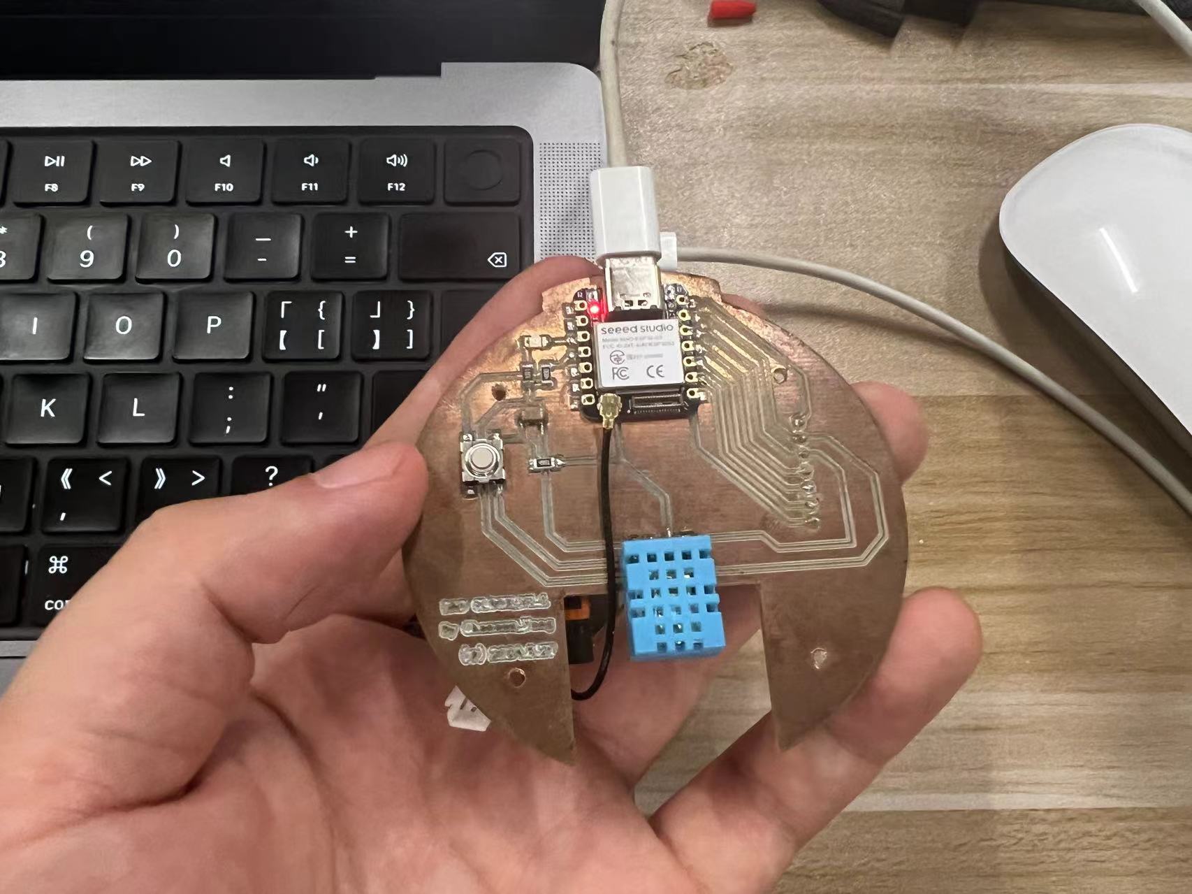
1. Hardware Connection
- I used the Dao clock Main board to test the DHT11,it already had DHT11 and XiaoESP32-S3
- Connect the Dao clock Main board to the computer using a USB cable.
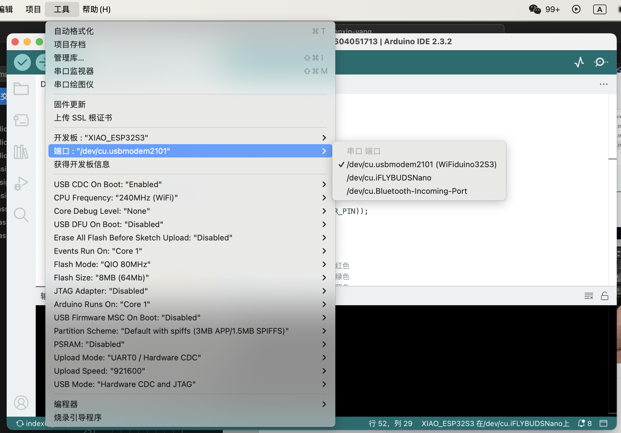
2. Software Configuration
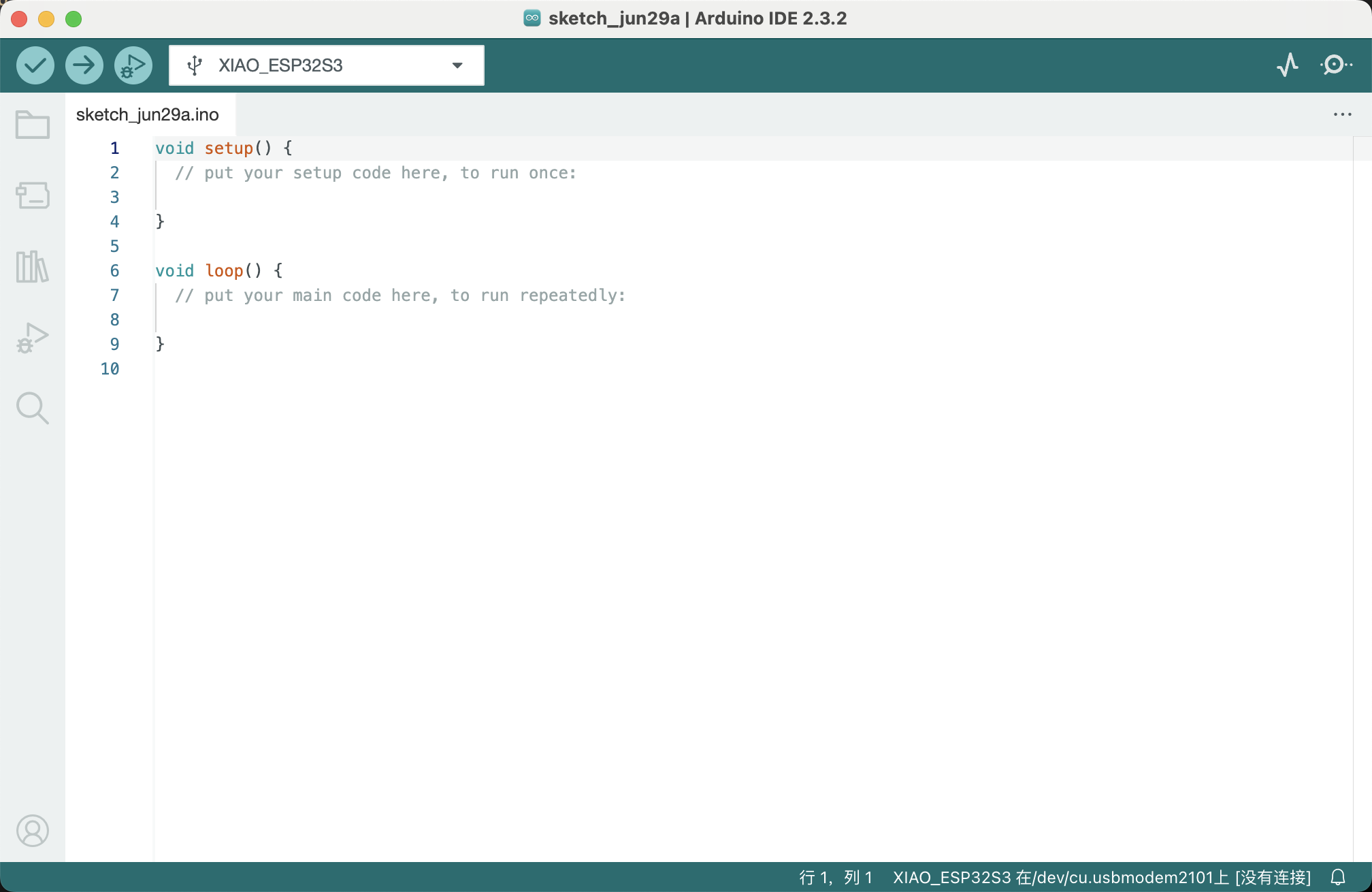
- Open the Arduino IDE and select the board and port for the ESP32-S3.
- Select the correct COM port for the board.
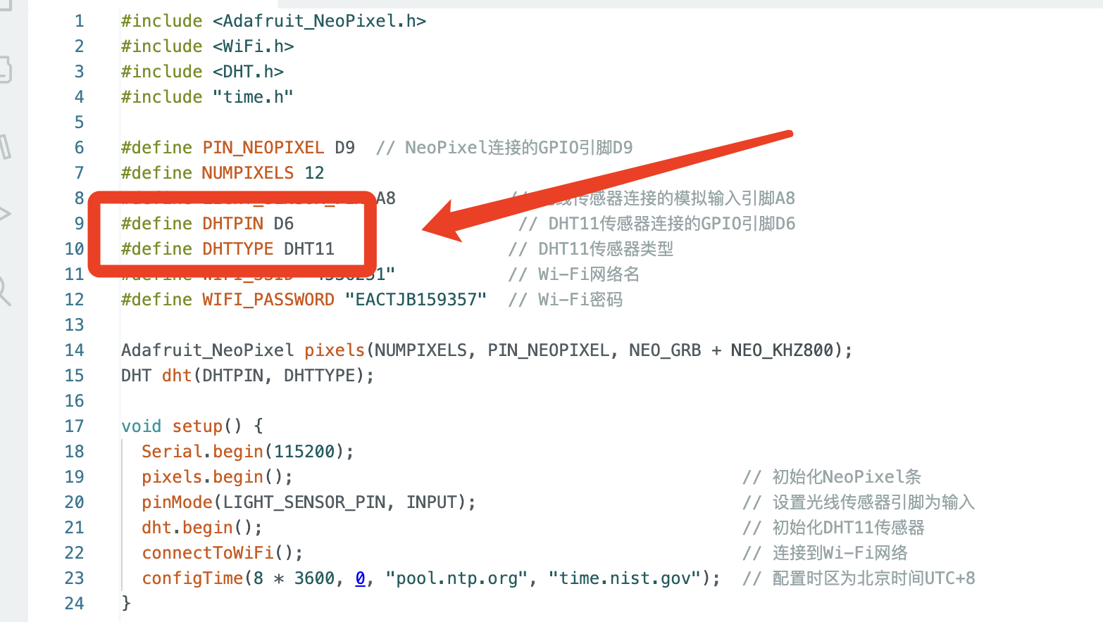
- Use a test Demo program
- Setup DHTPIN (D6): This GPIO pin D6 is allocated for the DHT11 sensor, which measures temperature and humidity, essential for environmental data gathering in your project.
- Upload the program to the ESP32-S3 board.
3.My program requirements
In my next program, I hope to set the temperature and humidity within a certain range as conditions to trigger other actions.
Therefore, I am adding conditions for temperature and humidity.
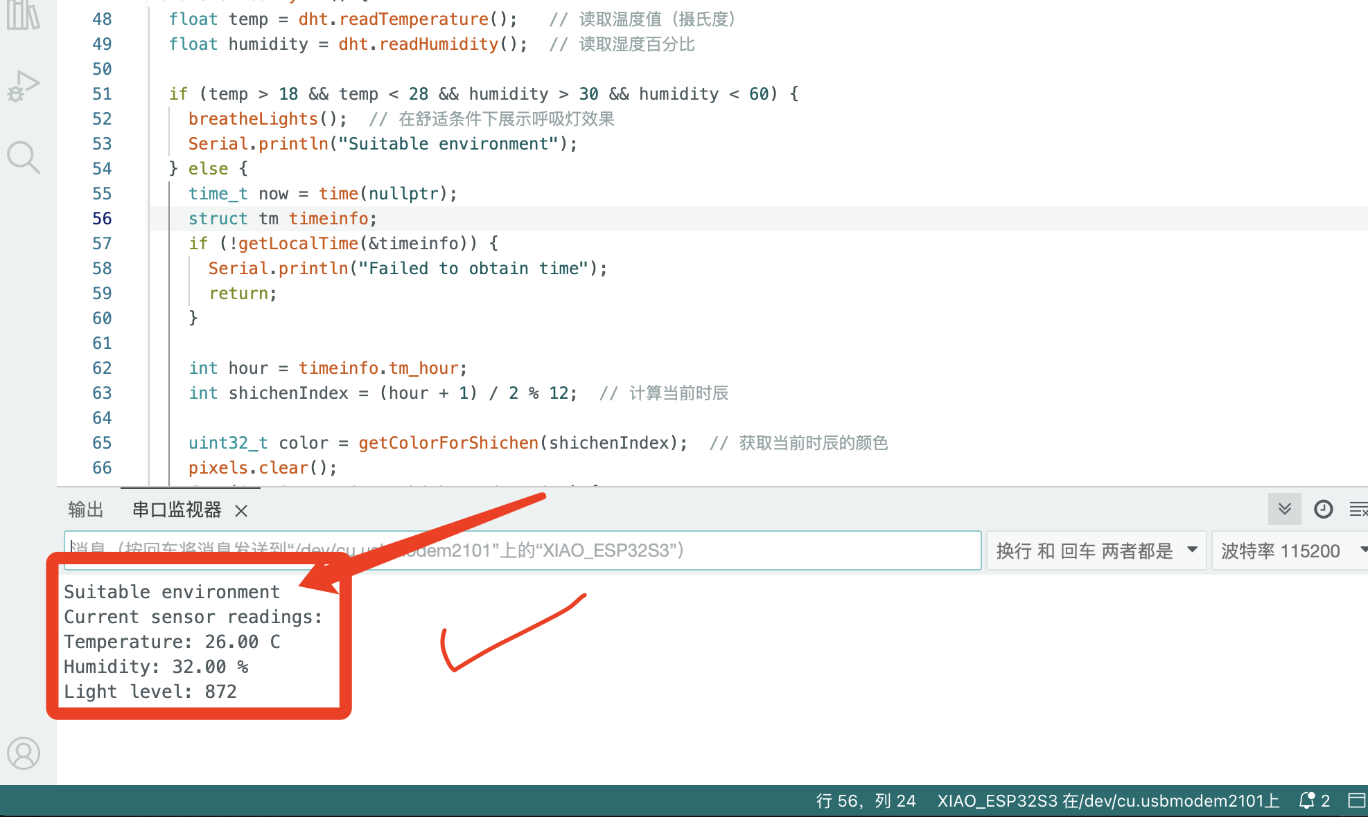
I will print the real-time temperature and humidity values on the serial monitor.
If they meet the required conditions, it will display "Suitable environment".

Here is the code for my program:
                    #include
                      #include
                      #include
                      #include "time.h"

                      #define PIN_NEOPIXEL D9  // NeoPixel连接的GPIO引脚D9
                      #define NUMPIXELS 12
                      #define LIGHT_SENSOR_PIN A8           // 光线传感器连接的模拟输入引脚A8
                      #define DHTPIN D6                      // DHT11传感器连接的GPIO引脚D6
                      #define DHTTYPE DHT11                 // DHT11传感器类型
                      #define WIFI_SSID "4536251"           // Wi-Fi网络名
                      #define WIFI_PASSWORD "EACTJB159357"  // Wi-Fi密码

                      Adafruit_NeoPixel pixels(NUMPIXELS, PIN_NEOPIXEL, NEO_GRB + NEO_KHZ800);
                      DHT dht(DHTPIN, DHTTYPE);

                      void setup() {
                        Serial.begin(115200);
                        pixels.begin();                                            // 初始化NeoPixel条
                        pinMode(LIGHT_SENSOR_PIN, INPUT);                          // 设置光线传感器引脚为输入
                        dht.begin();                                               // 初始化DHT11传感器
                        connectToWiFi();                                           // 连接到Wi-Fi网络
                        configTime(8 * 3600, 0, "pool.ntp.org", "time.nist.gov");  // 配置时区为北京时间UTC+8
                      }

                      void loop() {
                        int lightLevel = analogRead(LIGHT_SENSOR_PIN);       // 读取光线强度
                        int brightness = map(lightLevel, 0, 4095, 20, 255);  // 映射光线强度到亮度值,初始值20
                        pixels.setBrightness(brightness);                    // 设置LED亮度
                        showHourlyLED();                                     // 根据当前小时点亮LED
                        printSensorData();                                   // 打印传感器数据
                        delay(5000);                                        // 每30s更新一次
                      }

                      void connectToWiFi() {
                        Serial.println("Attempting to connect to WiFi network...");
                        WiFi.begin(WIFI_SSID, WIFI_PASSWORD);
                        while (WiFi.status() != WL_CONNECTED) {
                          delay(500);
                          Serial.print(".");
                        }
                        Serial.println("\nWiFi connected.");
                        Serial.print("IP address: ");
                        Serial.println(WiFi.localIP());
                      }

                      void showHourlyLED() {
                        float temp = dht.readTemperature();   // 读取温度值(摄氏度)
                        float humidity = dht.readHumidity();  // 读取湿度百分比

                        if (temp > 18 && temp < 28 && humidity > 30 && humidity < 60) {
                          breatheLights();  // 在舒适条件下展示呼吸灯效果
                          Serial.print("Suitable environment")
                        } else {
                          time_t now = time(nullptr);
                          struct tm timeinfo;
                          if (!getLocalTime(&timeinfo)) {
                            Serial.println("Failed to obtain time");
                            return;
                          }

                          int hour = timeinfo.tm_hour;
                          int shichenIndex = (hour + 1) / 2 % 12;  // 计算当前时辰

                          uint32_t color = getColorForShichen(shichenIndex);  // 获取当前时辰的颜色
                          pixels.clear();
                          for (int i = 0; i <= shichenIndex; i++) {
                            pixels.setPixelColor(i, color);  // 使用统一颜色设置点亮的LED
                          }
                          pixels.show();
                        }
                      }

                      void breatheLights() {
                        // 呼吸灯效果
                        for (int brightness = 20; brightness <= 128; brightness++) {
                          pixels.setBrightness(brightness);
                          pixels.show();
                          delay(10);
                        }
                        for (int brightness = 128; brightness >= 20; brightness--) {
                          pixels.setBrightness(brightness);
                          pixels.show();
                          delay(10);
                        }
                      }

                      void printSensorData() {
                        // 打印所有重要的传感器数据
                        Serial.println("Current sensor readings:");
                        Serial.printf("Temperature: %.2f C\n", dht.readTemperature());
                        Serial.printf("Humidity: %.2f %%\n", dht.readHumidity());
                        Serial.printf("Light level: %d\n", analogRead(LIGHT_SENSOR_PIN));
                      }

                      uint32_t getColorForShichen(int index) {
                          switch (index) {
                              case 0: return pixels.Color(20, 20, 20);     // 子时 - 玄黑
                              case 1: return pixels.Color(74, 66, 102);     // 丑时 - 黛色
                              case 2: return pixels.Color(61, 59, 79);     // 寅时 - 鸦青
                              case 3: return pixels.Color(237, 87, 54);   // 卯时 - 妃色
                              case 4: return pixels.Color(255, 241, 67);   // 辰时 - 藤黄
                              case 5: return pixels.Color(249, 144, 111);   // 巳时 - 酡颜
                              case 6: return pixels.Color(157, 41, 51);   // 午时 - 胭脂
                              case 7: return pixels.Color(72, 192, 163);   // 未时 - 天水碧
                              case 8: return pixels.Color(217, 182, 17); // 申时 - 秋香
                              case 9: return pixels.Color(115, 151, 171); // 酉时 - 花青
                              case 10: return pixels.Color(93, 81, 60);    // 戌时 - 相思灰
                              case 11: return pixels.Color(214, 236, 240);    // 亥时 - 月白
                              default: return pixels.Color(255, 255, 255); // 默认 - 白色
                          }
                      }
5.Some Problems and Solutions.
1. DHT11 not working properly.
When I completed my first PCB design, I was the fastest progressing member in our group.However, during the subsequent program testing, I found that the DHT11 was not functioning properly, and I smelled something burning.
I realized there must have been a short circuit somewhere.
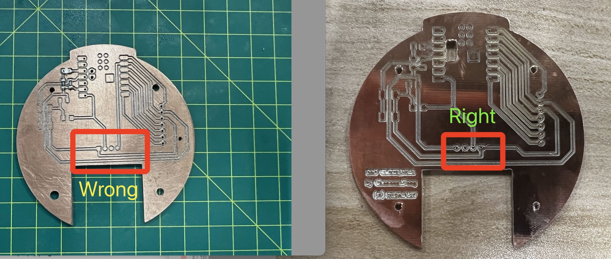
After attempting to troubleshoot many times and burning out another DHT11 sensor, I discovered that a flaw in the circuit board design had caused me to connect the pins incorrectly, thereby damaging the DHT11 component.
The circuit board I showed earlier is the correctly adjusted final design.
Now, I'm also sharing the failed version.
This reminds me to carefully and meticulously review the component datasheets to ensure correct installation.
2.Do not get the correct temperature and humidity values.
I found that the I forgot to correct the pin connections for the DHT11 sensor.After correcting the pin connections, I was able to get the correct temperature and humidity values.
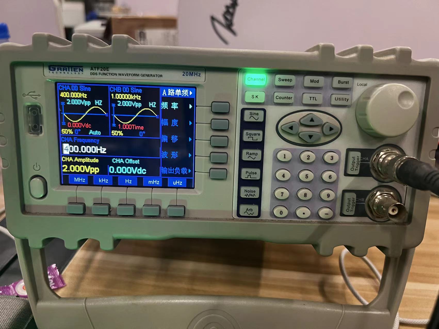
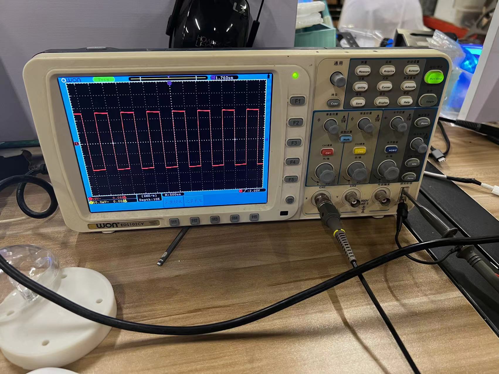
6.Using the Oscilloscope to Measure waveforms
1. Set up the Oscilloscope:
- Connect the power and turn on the oscilloscope.
- Connect the probe to the oscilloscope.
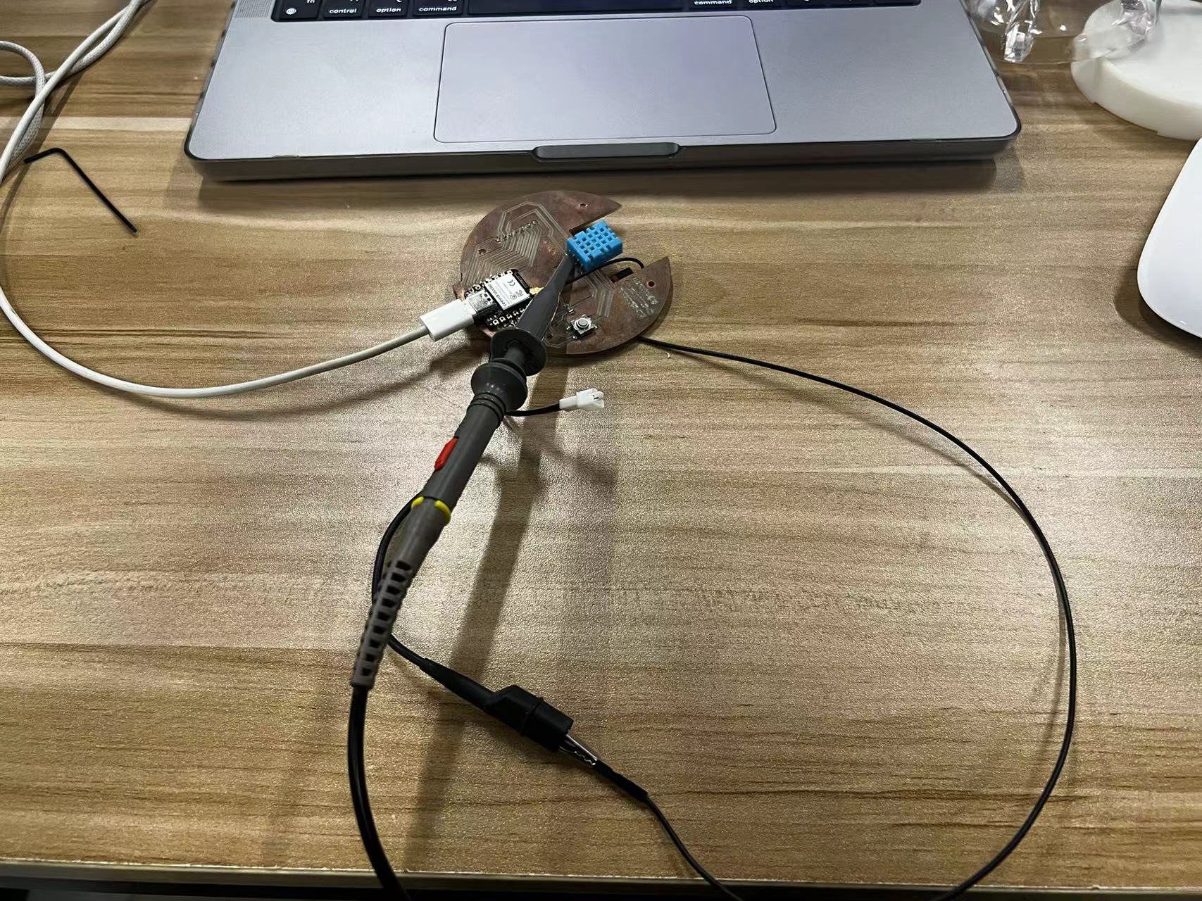
2. Connect the Probe:
- Attach the ground clip of the probe to the circuit ground.
- Connect the tip of the probe to the test point on the circuit.
3. Adjust Settings:
- Set the vertical (voltage) and horizontal (time) scales to appropriate ranges.
- Adjust the position controls to center the waveform.
4. Trigger Settings:
- Set the trigger level to stabilize the waveform.
- Choose the appropriate trigger source and mode.
5. Analyze the Signal:
- Observe the amplitude, frequency, and any abnormalities in the waveform.
- Use measurement tools to analyze waveform characteristics.
The Hero Shots
Here's my hero shot for this week.

Team Assignment
Group Assignment link.
Oscilloscope
An oscilloscope is a crucial tool in electronics, enabling the visualization of electrical signal voltages as waveforms over time.
It offers various features:
• **Display:** Shows electrical signals as waveforms, with voltage on the vertical axis and time on the horizontal axis.
• **Channels:** Allows multiple signals to be viewed simultaneously.
• **Bandwidth:** Determines the frequency range the oscilloscope can measure accurately.
• **Sampling Rate:** The rate at which the oscilloscope samples the signal, crucial for capturing fast-changing signals.
• **Triggering:** Stabilizes repeating signals by starting data capture at a specific signal point.
Assignment files
Let's Jump to the Top !!!